The basic ideal reactor types
*

The basic types are ? you know them, or ?...
more?

The characterization of the 3 basic (ideal) reactor types
There are two points of view for the characterization of
the basic reactor types:
- the characteristics of macro-mixing,
represented by the residence time distribution (RTD),( - see answer to
the question: 'which information do you get from the RTD ?'
for further details).
In this case you 'see only' information on the
vessel's mixing-behaviour as you get it by labelling with an inert tracer. I
want to visualize the 'mere mixing bevaviour' as we could see it with our bare
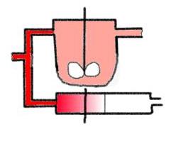
eyes when a colour tracer is applied in a very simple animation. The red colour
tracer is added in a step function, - the response is the cumulative RTD. The
draft can be seen here (animated gif, about 600 k):
 Don't forget: no
reaction!!
You see the moving plug flow front in the ideal TFR (is that
realistic ??) and the steadily growing red of the colour in the CSTR . When the
cumulative RTD is finished, the system starts again with the tracer
concentration switched off simultaneously, here you see the signal course of
the 'displacement method', the tracer fluid (colour solution) gets displaced by
the pure 'basic fluid' (solvent, e.g. water). Did you know that for the ideal
CSTR, and only for this reactor, the displacement curve represents the RTD
spectral curve ?!!
- the (typical) concentration course as you can
measure it when carrying out an experiment with a 'running' reaction. (But
don't forget that the mixing-behaviour is an information that is
immanent in the concentration course)
Therefore: 'More' information on the behaviour under
reaction conditions can be received by regarding the concentration curves vs.
time and space (length, volume) in the 3 basic types when carrying out a simple
reaction in the reactors:*

- the batch stirred tank reactor:
concentration is is constant overall in the whole vessel (stationary in space
and totally back-mixed in space) but it is dropping down with the time ( not
stationary in time, - that is equivalent to 'not back-mixed in time' but this
statement may be a bit less understandable), this can also be seen by the
different constant concentration levels in space that are dropping down with
time (parallel lines!). The reactor is not stationary in (both) space .. and
time.
- the continuous tubular flow reactor:
concentration is constant over the time at different length positions along the
tube ( parallel lines with the parameter L), it is stationary in time. But the
reactor is not stationary in space, as you can see from the concentration
dropping down along the reactor length, - the reactor is not stationary in
space. The reactor is 'not-back-mixed' in space (concentration gradient along
reactor length). The reactor is not stationary in (both) space ..and
time.
- the continuous stirred tank reactor:
concentration is stationary in space and time. The reactor is totally
back-mixed in space and time. The reactor is stationary in space and time. But you have to
realize: that is valid only for the reactor when running stationary, not in the
start-up- , shutdown- or disturbed operation phase !!!!

|
*And once again:
the
statements above are made for the reactors with a 'running' reaction inside, do
not change that with the properties of macro-mixing alone, as characterized by
the RTD from an inert tracer signal. But - as already mentioned - the
macro-mixing properties are the cause for the whole behaviour. What is the
difference ? Take a very simple statement: With a RTD experiment the inert
tracer is diluted by the convective flow and disappears on account of that
dilution. The 'running' chemical reaction makes together with the convective
flow the educts disappear, products appear and disappear, concentrations
change, kinetics get influenced. You see the difference between 'only' RTD and
'reaction running' very comprehensive, when you regard a serial combination of
an ideal CSTR and an ideal TFR: for the RTD it is not important, which reactor
type is the first of the series, - wheres for a running reaction this topic
becomes 'decisive' (see general remarks on reactor combinations and especially two
graphs showing the two alternatives of a series
combination TFR/CSTR for a simple 1st order reaction). By the way: think about
the question whether a RTD for a STR makes any sense in practice. First of all:
you can not add a step function to a 'batch' (true or not?). But you could
perhaps add a Dirac pulse to a STR. What would you see: you could see the
mixing quality of the tank, isn't it? In spite of being interesting, this
information is not a RTD in the usual sense.
And:
never take the word 'reaction' into your mouth, when
talking about RTD, - unless you are a specialist and talking about
'reactive marking in RTD' ! The 'normal' RTD doesn't characterize reactive
behaviour ! But: both aspects (RTD and reactive
system) are entirely represented by the material balance of the reactor.
Only in the case of the RTD the term of the chemical reaction is omitted
in the material balance, - and when you solve the material balance equation for
this case, you get the observable function of the RTD.
For
a visualized example I want to show you a 'virtual snapshot' of an 'open'
parallel combination of an ideal CSTR and a TFR. The continuous reactor system
is running stationary and a reaction is carried out in it where a red
dye is decomposing to a colorless product in a 'definite reaction' started at
the reactor inlets ( thermal or light induction or something like that). In the
CSTR you get some rest colour corresponding to the reached conversion, whereas
in the TFR you see a gradient of the colour along the tube, ending at the white
colour of the solvent. I tried to put a black line to the place where the
colour is the same as in the CSTR. With this line I wanted to demonstrate that
the same conversion can be reached in the TFR within a clearly smaller reactor
volume. 
Realize: reaction takes place !!!
The colour
gradient along the tube is a bit dense, but I think you realize the intention.
Did you realize that we need no animation here, because in the stationary state
we would have always the same image (repeatedly) ? !
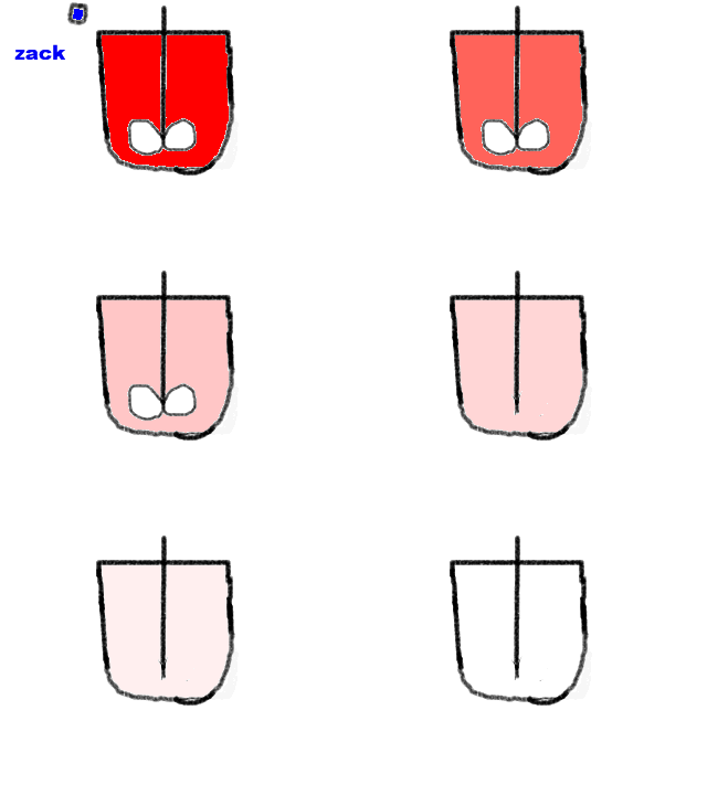
In
a further animation you see (repeatedly) the colour decay in a batch STR, where
the 'x-coordinate' for the concentration gradient is the time axis (compare to
the graph on top ):

Realize: reaction takes place
!!!
here you need an animation for a good visualization!!
back to top |

Immediate test of your knowledge:
Do you now
understand the following statements?
A CSTR is working stationary
in space and time, it is
'totally' back-mixed
A Batch STR is working stationary
only in space, but not in time, it is only back-mixed in space, but
not in time
A TFR is working stationary in
time, but not in space (there is a gradient along the length-axis), it
is not-back-mixed in space
|
No ? Then you should go to the - what we say in
German - 'rural guard force academy' (Redewendung: 'zum Feldschütz in die
Schule gehen'). I can not help you more, try to regard the graph again! Or: my
last help, but that is only a repetition
! |
back to top

Important 'Add-on' to the classification of basic reactor types
Mainly in context with reactors for heterogeneous
systems - but also as a general mode of reactor classification - we can
define:
- *integral
reactors:
Integral reactors are reactors running in a high
conversion mode. They are 'good' reactors for high specific product
efficiencies. Fixed bed reactors with considerable heights of the fixed bed are
typical integral reactors (integral TFR). For kinetic measurements the integral
reactors are problematic, as they exhibit a concentration gradient along the
fixed bed and the solution of their material balance demands an integration.
For this integration you normally have to know your reaction kinetics, - but
that is what you want to measure when carrying out kinetic measurements
!!
- *differential
reactors:
Differential reactors are running in a very low
conversion mode. They are 'good' reactors for kinetic measurements. When the
conversion is infinitesimally small, our conversion represents directly the
reaction rate. The only disadvantage of these reactors are the analytical
problems caused by the minimal difference between inlet- and
outlet-concentrations. Typical differential reactors are fixed bed reactors
with very low fixed bed heights. For getting rid of the problem of very small
concentration differences we can take the differential loop reactor with high
recirculation factors. Here we get an 'enhancement' by multiple passing of the
'differential bed' and as a further advantage that we can use the material
balance of a CSTR for the differential loop reactor with high
recirculation.
back to top

And last not least a more complicated question: what
makes the relationship between batch STR and continuous TFR, what is their
difference to the CSTR, - and what is the difference between them among
themselves ? help?

take your browser back for previous text or:
 to main test page
![]()
![]()
 Don't forget: no
reaction!!
![]()


![]()